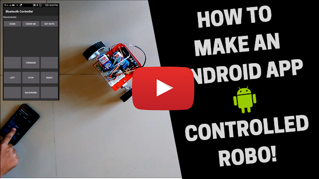
Android App Controlled ROBO!

In this project we are going to develop a Bluetooth controlled ROBO car. Here we used a Bluetooth module to control the car, and it is also an Android based Application.
Components required
- Arduino UNO
- RC Car Chassis
- DC Motors
- Bluetooth Module HC-05
- Motor Driver IC L293D
- Two 9V Battery
- Battery Connectors
Bluetooth controlled car is controlled by using Android mobile phone instead of any other method like buttons, gesture etc. Here only needs to touch button in android phone to control the car in forward, backward, left and right directions. So here android phone is used as transmitting device and Bluetooth module placed in car is used as receiver. Android phone will transmit command using its in-built Bluetooth to car so that it can move in the required direction like moving froward, reverse, turning left, turning right and stop.
Bluetooth
Module
HC
Bluetooth module consists two things one is Bluetooth serial interface
module and a Bluetooth adaptor. Bluetooth serial module is used for converting
serial port to Bluetooth.
How
to operate Bluetooth module?
You
can directly use the Bluetooth module after purchasing from market, because
there is no need to change any setting of Bluetooth module. Default baud rate
of new Bluetooth module is 9600 bps. You just need to connect rx and tx to
controller or serial converter and give 5 volt dc regulated power supply to
module.
Working
To run
this project first we need to download Bluetooth app form Google play store. We
can use any Bluetooth app that supporting or can send data. Here are some
apps' name that might work correctly.
-
Bluetooth Spp pro
-
Bluetooth controller
After
installing app you need to open it and then search Bluetooth device and
select desired Bluetooth device. And then configure keys. Here in this
project we have used Bluetooth controller app.
- Download and install Bluetooth Controller.
- Turned ON mobile Bluetooth.
- Now open Bluetooth controller app
- Press scan
- Select desired Bluetooth device
- Now set keys by pressing set buttons on screen. To set keys we need to press ‘set button’ and set key according to picture given below:

After
setting keys press ok.
When
we touch forward button in Bluetooth controller app then car start moving in
forward direction and moving continues forward until next command comes.
When
we touch backward button in Bluetooth controller app then car start moving in
reverse direction and moving continues reverse until next command comes.
When
we touch left button in Bluetooth controller app then car start moving in left
direction and moving continues left until next command comes. In this condition
front side motor turns front side wheels in left direction and motor runs in
forward direction.
When
we touch right button in Bluetooth controller app then car start moving in
right direction and moving continues right until next command comes. In this
condition front side motor turns front side wheels in right direction and motor
runs in forward direction.
And
by touching stop button we can stop the car.
Circuit Diagram and Explanation:

Circuit
diagram for Bluetooth controlled car is shown in above figure. A Motor
driver is connected to Arduino to run the car. Motor driver’s input pins
2, 7, 10 and 15 are connected to Arduino’s digital pin number 12, 11, 10
and 9 respectively. Here we have used two DC motors to driver car in which one
motor is connected at output pin of motor driver 3 and 6 and another motor is
connected at 11 and 14. A 6 volt Battery is also used to power the motor
driver for driving motors. Bluetooth module’s rx and tx pins are directly connected
at tx and rx of Arduino. And vcc and ground pin of Bluetooth module is
connected at +5 volt and gnd of Arduino. And a 9 volt battery is used for power
the circuit at Arduino’s Vin pin.
Code:
#define m11 11 // rear motor
#define m12 12
#define m21 10 // front motor
#define m22 9
char str[2],i;
void forward()
{
digitalWrite(m11, HIGH);
digitalWrite(m12, LOW);
delay(100);
digitalWrite(m21, HIGH);
digitalWrite(m22, LOW);
}
void backward()
{
digitalWrite(m11, LOW);
digitalWrite(m12, HIGH);
digitalWrite(m21, LOW);
digitalWrite(m22, HIGH);
}
void left()
{digitalWrite(m11, LOW);
digitalWrite(m12, LOW);
delay(100);
digitalWrite(m21, HIGH);
digitalWrite(m22, LOW);
}
void right()
{
digitalWrite(m11, HIGH);
digitalWrite(m12, LOW);
digitalWrite(m21, LOW);
digitalWrite(m22, LOW);
}
void Stop()
{
digitalWrite(m11, LOW);
digitalWrite(m12, LOW);
digitalWrite(m21, LOW);
digitalWrite(m22, LOW);
}
void setup()
{
Serial.begin(9600);
pinMode(m11, OUTPUT);
pinMode(m12, OUTPUT);
pinMode(m21, OUTPUT);
pinMode(m22, OUTPUT);
}
void loop()
{
while(Serial.available())
{
char ch=Serial.read();
str[i++]=ch;
if(str[i-1]=='1')
{
Serial.println("Forward");
forward();
i=0;
}
else if(str[i-1]=='2')
{
Serial.println("Left");
right();
i=0;
}
else if(str[i-1]=='3')
{
Serial.println("Right");
left();
i=0;
}
else if(str[i-1]=='4')
{
Serial.println("Backward");
backward();
i=0;
}
else if(str[i-1]=='5')
{
Serial.println("Stop");
Stop();
i=0;
}
delay(100);
}
}
Download the full document and code here: Download PDF
Click below to watch the video:


Comments
Post a Comment