Basic things about Arduino (Arduino Series - Part 01)

Arduino is a prototype platform (open-source) based on an easy-to-use hardware and software. It consists of a circuit board, which can be programed (referred to as a microcontroller) and a ready-made software called Arduino IDE (Integrated Development Environment), which is used to write and upload the computer code to the physical board.
Arduino provides a standard form factor that breaks the functions of the micro-controller into a more accessible package.
Arduino Board Description

1. Power USB
Arduino board can be powered by using the USB cable from your computer. All you need to do is connect the USB cable to the USB connection.
2. Power (Barrel Jack)
Arduino boards can be powered directly from the AC mains power supply by connecting it to the Barrel Jack.
3. Arduino Reset
You can reset your Arduino board, i.e., start your program from the beginning. You can reset the UNO board in two ways. First, by using the reset button (17) on the board. Second, you can connect an external reset button to the Arduino pin labelled RESET.
4. Pins (3.3, 5, GND, Vin)
- 3.3V (6) − Supply 3.3 output volt
- 5V (7) − Supply 5 output volt
- Most of the components used with Arduino board works fine with 3.3 volt and 5 volt.
- GND (8)(Ground) − There are several GND pins on the Arduino, any of which can be used to ground your circuit.
- Vin (9) − This pin also can be used to power the Arduino board from an external power source, like AC mains power supply.
5. Analog pins
The Arduino UNO board has six analog input pins A0 through A5. These pins can read the signal from an analog sensor like the humidity sensor or temperature sensor and convert it into a digital value that can be read by the microprocessor.
6. Main microcontroller
Each Arduino board has its own microcontroller (11). You can assume it as the brain of your board. The main IC (integrated circuit) on the Arduino is slightly different from board to board. The microcontrollers are usually of the ATMEL Company. You must know what IC your board has before loading up a new program from the Arduino IDE. This information is available on the top of the IC. For more details about the IC construction and functions, you can refer to the data sheet.
7. Digital I/O
The Arduino UNO board has 14 digital I/O pins (15) (of which 6 provide PWM (Pulse Width Modulation) output. These pins can be configured to work as input digital pins to read logic values (0 or 1) or as digital output pins to drive different modules like LEDs, relays, etc. The pins labeled “~” can be used to generate PWM.
Arduino Installation
After learning about the main parts of the Arduino UNO board, we are ready to learn how to set up the Arduino IDE. Once we learn this, we will be ready to upload our program on the Arduino board.
In this section, we will learn in easy steps, how to set up the Arduino IDE on our computer and prepare the board to receive the program via USB cable.
Step 1 − First you must have your Arduino board (you can choose your favorite board) and a USB cable. In case you use Arduino UNO, Arduino Duemilanove, Nano, Arduino Mega 2560, or Diecimila, you will need a standard USB cable (A plug to B plug), the kind you would connect to a USB printer as shown in the following image.

Step 2 − Download Arduino IDE Software.
You can get different versions of Arduino IDE from the Download page on the Arduino Official website. You must select your software, which is compatible with your operating system (Windows, IOS, or Linux). After your file download is complete, install it.
Step 3 − Power up your board.
The Arduino Uno, Mega, Duemilanove and Arduino Nano automatically draw power from either, the USB connection to the computer or an external power supply. If you are using an Arduino Diecimila, you have to make sure that the board is configured to draw power from the USB connection. The power source is selected with a jumper, a small piece of plastic that fits onto two of the three pins between the USB and power jacks. Check that it is on the two pins closest to the USB port.
Connect the Arduino board to your computer using the USB cable. The green power LED (labeled PWR) should glow.
Step 4 − Launch Arduino IDE.
After your Arduino IDE software is downloaded, you need to unzip the folder. Inside the folder, you can find the application icon with an infinity label (application.exe). Double-click the icon to start the IDE.

Step 5 − Open your first project.
Once the software starts, you have two options −
- Create a new project.
- Open an existing project example.
To create a new project, select File → New.

To open an existing project example, select File → Example → Basics → Blink.

Here, we are selecting just one of the examples with the name Blink. It turns the LED on and off with some time delay. You can select any other example from the list.
Step 6 − Select your Arduino board.
To avoid any error while uploading your program to the board, you must select the correct Arduino board name, which matches with the board connected to your computer.
Go to Tools → Board and select your board.

Here, we have selected Arduino Uno board according to our tutorial, but you must select the name matching the board that you are using.
Step 7 − Select your serial port.
Select the serial device of the Arduino board. Go to Tools → Serial Port menu. This is likely to be COM3 or higher (COM1 and COM2 are usually reserved for hardware serial ports). To find out, you can disconnect your Arduino board and re-open the menu, the entry that disappears should be of the Arduino board. Reconnect the board and select that serial port.

Step 8 − Upload the program to your board.
Before explaining how we can upload our program to the board, we must demonstrate the function of each symbol appearing in the Arduino IDE toolbar.
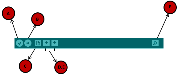
A − Used to check if there is any compilation error.
B − Used to upload a program to the Arduino board.
C − Shortcut used to create a new sketch.
D − Used to directly open one of the example sketch.
E − Used to save your sketch.
F − Serial monitor used to receive serial data from the board and send the serial data to the board.
Now, simply click the "Upload" button in the environment. Wait a few seconds; you will see the RX and TX LEDs on the board, flashing. If the upload is successful, the message "Done uploading" will appear in the status bar.
Note − If you have an Arduino Mini, NG, or other board, you need to press the reset button physically on the board, immediately before clicking the upload button on the Arduino Software.
Click below to watch a full Tutorial video on it:
Click below to watch a full Tutorial video on it:


Comments
Post a Comment