Interfacing LCD with Arduino (Arduino Series - Part 04)

In Arduino based embedded system design, the Liquid Crystal Display modules play a very important role. Hence it is very important to learn about how to interface LCD with an Arduino of 16×2 in embedded system design. The display units are very important in communication between the human world and the machine world. The display unit work on the same principle, it does not depend on the size of the display it may be big or the small. We are working with the simple displays like 16×1 and 16×2 units. The 16×1 display unit has the 16 characters which present in one line and 16×2 display units have 32 characters which are present in the 2 line. We should know that to display the each character there are 5×10 pixels. Thus to display one character all the 50 pixels should be together. In the display,there is a controller which is HD44780 it is used to control the pixels of characters to display.
What is a Liquid Crystal Display?
The liquid crystal display uses the property of light monitoring of liquid crystal and they do not emit the light directly. The Liquid crystal display is a flat panel display or the electronic visual display. With low information, content the LCD’ s are obtained in the fixed image or the arbitrary image which are displayed or hidden like present words, digits, or 7 segment display. The arbitrary images are made up of large no of small pixels and the element has larger elements.
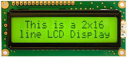
Liquid Crystal Display of 16×2
The 16×2 liquid crystal display contains two horizontal lines and they are used for compressing the space of 16 display characters. In inbuilt, the LCD has two registers which are described below.
- Command Register
- Data Register
Command Register: This register is used to insert a special command in the LCD. The command is a special set of data and it is used to give the internal command to the liquid crystal display like clear screen, move to line 1 character 1, setting the curser and etc.
Data Register: The data registers are used to enter the line in the LCD
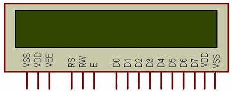
Pin diagram and description of each pin have explained in the following table.
| Pin No | Pin Name |
Pin Description
|
Pin 1
|
GND
|
This pin is a ground pin and the LCD is connected to the Ground
|
Pin 2
|
VCC
|
The VCC pin is used to supply the power to the LCD
|
Pin 3
|
VEE
| This pin is used for adjusting the contrast of the LCD by connecting the variable resistor in between the VCC & Ground. |
Pin 4
|
RS
| The RS is known as register select and it selects the Command/Data register. To select the command register the RS should be equal to zero. To select the Data register the RS should be equal to one. |
Pin 5
|
R/W
| This pin is used to select the operations of Read/Write. To perform the write operations the R/W should be equal to zero. To perform the read operations the R/W should be equal to one. |
Pin 6
|
EN
|
This is a enable signal pin if the positive pulses are passing through a pin, then the pin function as a read/write pin.
|
Pin 7
|
DB0 to DB7
| The pin 7 contains total 8 pins which are used as a Data pin of LCD. |
Pin 15
|
LED +
|
This pin is connected to VCC and it is used for the pin 16 to set up the glow of backlight of LCD.
|
Pin 16
|
LED –
|
This pin is connected to Ground and it is used for the pin 15 to set up the glow of backlight of the LCD.
|
LCD Interfacing with the Arduino Module
The following circuit diagram shows the liquid crystal display with the Arduino module. From the circuit diagram, we can observe that the RS pin of the LCD is connected to the pin 12 of the Arduino. The LCD of R/W pin is connected to the ground. The pin 11 of the Arduino is connected to the enable signal pin of LCD module. The LCD module & Arduino module are interfaced with the 4-bit mode in this project. Hence there are four input lines which are DB4 to DB7 of the LCD. This process very simple, it requires fewer connection cables and also we can utilize the most potential of the LCD module.
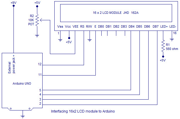
The digital input lines (DB4-DB7) are interfaced with the Arduino pins from 5-2. To adjust the contrast of the display here we are using a 10K potentiometer. The current through the back LED light is from the 560-ohm resistor. The external power jack is provided by the board to the Arduino. Using the PC through the USB port the Arduino can power. Some parts of the circuit can require the +5V power supply it is taken from the 5V source on the Arduino board.
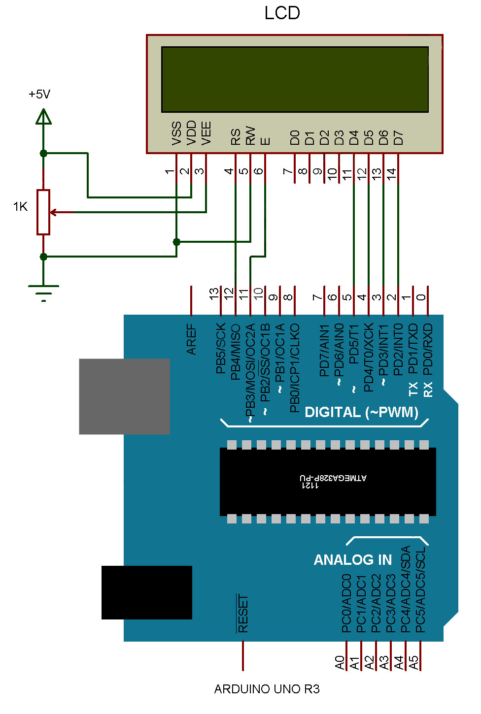
The following schematic diagram shows the LCD module interfacing with the Arduino.
Code:
/*
LiquidCrystal Library - Hello World
Demonstrates the use a 16x2 LCD display. The LiquidCrystal
library works with all LCD displays that are compatible with the
Hitachi HD44780 driver. There are many of them out there, and you
can usually tell them by the 16-pin interface.
This sketch prints "Hello World!" to the LCD
and shows the time.
The circuit:
* LCD RS pin to digital pin 12
* LCD Enable pin to digital pin 11
* LCD D4 pin to digital pin 5
* LCD D5 pin to digital pin 4
* LCD D6 pin to digital pin 3
* LCD D7 pin to digital pin 2
* LCD R/W pin to ground
* LCD VSS pin to ground
* LCD VCC pin to 5V
* 10K resistor:
* ends to +5V and ground
* wiper to LCD VO pin (pin 3)
Library originally added 18 Apr 2008
by David A. Mellis
library modified 5 Jul 2009
by Limor Fried (http://www.ladyada.net)
example added 9 Jul 2009
by Tom Igoe
modified 22 Nov 2010
by Tom Igoe
modified 7 Nov 2016
by Arturo Guadalupi
This example code is in the public domain.
http://www.arduino.cc/en/Tutorial/LiquidCrystalHelloWorld
*/
// include the library code:
#include <LiquidCrystal.h>
// initialize the library by associating any needed LCD interface pin
// with the arduino pin number it is connected to
const int rs = 12, en = 11, d4 = 5, d5 = 4, d6 = 3, d7 = 2;
LiquidCrystal lcd(rs, en, d4, d5, d6, d7);
void setup() {
// set up the LCD's number of columns and rows:
lcd.begin(16, 2);
// Print a message to the LCD.
lcd.print("hello, world!");
}
void loop() {
// set the cursor to column 0, line 1
// (note: line 1 is the second row, since counting begins with 0):
lcd.setCursor(0, 1);
// print the number of seconds since reset:
lcd.print(millis() / 1000);
}
Click below to watch a full Tutorial on it:


This blog is really helpful to deliver updated educational affairs over internet which is really appraisable. I found one successful example of this truth through this blog. I am going to use such information now. lcd display
ReplyDeleteOutstanding as well as powerful tip by the writer of this blog are really handy to me. Integrated circuits
ReplyDeleteThanks for sharing the best information and suggestions, If you are looking for the best transparent led screen, then visit zoomvisual.com.sg. Highly energetic blog, I’d love to find out some additional information.
ReplyDeleteThanks for sharing the best information and suggestions, If you are looking for the best transparent led screen, then visit zoomvisual.com.sg. Highly energetic blog, I’d love to find out some additional information.
ReplyDeleteHello sir
ReplyDeleteSir can you make video on how to make UPI payment method for any project using arduino uno. Please sir make video on this topic if you can 🙏. It will help me a lot .
Thanks.
ok, thank you very much
ReplyDeleteit can help me
i like them
http://www.viewelcd.com/tft-lcm/
LCD Panel
DeleteLCD Module
LCD screen
Very informative and impressive post you have written, this is quite interesting and i have went through it completely, an upgraded information is shared, keep sharing such valuable information. Find the best stretched lcd.
ReplyDeleteWhich language is for the Arduino programming? And which language you use in your YouTube video
ReplyDelete